Honeywell Thermostat Wiring For Heat Pumps
Ready to take charge of your home’s comfort? Look no further! Our ultimate guide to Honeywell thermostat wiring is here to empower you. Say goodbye to confusion and hello to seamless installation or replacement. From single-stage simplicity to multi-stage mastery, we’ve got you covered.
Before we go into the actual wiring tutorials let’s look at the honeywell thermostat wiring code just to familiarize yourself with the wire colors and the function.
Honeywell thermostat wiring color code
| Wire Color | Terminal | Function |
| Red | R/Rh/Rc | Power (24VAC) |
| Blue | C | Common (24VAC) |
| White | W/W1 | Heat relay (Stage 1) |
| Brown | W2 | Heat relay (stage 2) |
| Green | G | Fan relay |
| Yellow | Y/Y1 | Compressor contactor (Stage 1) |
| Light blue/ others | Y2 | Compressor contactor (Stage 2) |
| Orange | O/O/B | Reversing valve (Cooling/Heat pump) |
| Brown | E/Aux/W2 | Emergency heat |
| Not fixed | L/A | Heat Pump fault input |
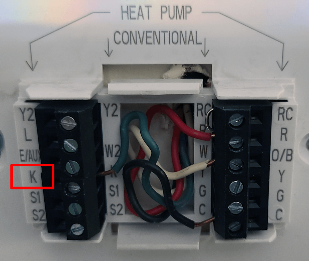
| Not fixed | K | Honeywell saver module |
| Not fixed | S | Outdoor temperature sensor |
| Not fixed | U | Unused |
Preparing your thermostat for wiring
Here are some notes on preparing your thermostat for wiring:
1. Turn Off Power: Ensure that the power to your heating and cooling system is turned off. This can usually be done by switching off the circuit breaker that controls the HVAC system. It is crucial to prevent any electrical accidents during the wiring process.
2. Remove Old Thermostat: Carefully remove the old thermostat from the wall. Take note of the wires connected to each terminal and their corresponding labels.
3. Take a Photo: Before disconnecting any wires, take a clear photo of the wiring configuration. This will serve as a reference during the installation of the Nest thermostat.
4. Label Existing Wires: If you are replacing an existing thermostat, label each wire according to its terminal designation. This will help you match the wires correctly to the corresponding terminals on your new thermostat.
Read also: Honeywell AC not cooling
5. Secure the Wires: To prevent the wires from falling back into the wall, use a small piece of tape to secure them to the wall temporarily. Alternatively, you can use a pen or pencil to gently thread the wires through and secure them in place.
6. Mount the Nest Base: Install the Nest thermostat base on the wall using the provided screws and a screwdriver. Make sure it is securely mounted and level.
Prepare Wires: If needed, strip the ends of the wires to expose a sufficient length for proper connection at least ⅓ inches. Remove any excess insulation and ensure that the wire strands are neat and undamaged.
Read also: Nest Thermostat Wiring For Heat Pump
Things your need to be aware of before replacing your old thermostat with a new honeywell
- If your system is a heat only system, ensure to buy a thermostat that supports that type. There are also some thermostats that support only heat pumps.
- For example, you may only have 3 wires on your thermostat. Usually thermostats that support heat pumps only will not have the W terminal for heat.
Honeywell 1st Stage Heat Pump System with 1 Compressor (6 Wire)
With a first stage heat pump system you will typically have 6 wires. These wires will include the Fan relay for controlling the fan, the O/B reverse valve responsible for switching between the heat and cool mode.
However, with a single stage heat pump system you should only have 1 Y wire for the compressor relay. This wire is responsible for energizing the compressor.
If your wiring comes with separate R wires( R and Rc) then connect both of them onto the separate thermostat terminals.
However if you only have wire R wire, you are going to connect it to one of the terminals and put a jumper between them.
For Honeywell pro series thermostat thermostats, If there is only one R wire, and it is connected to the R, Rc, or RH terminal, set the slider tap to the up position (1 wire).
But if there is one wire connected to the R terminal and one wire connected to the Rc terminal, set the slider to the down position (2 wires)
Read also: Carrier Infinity Thermostat Wiring To Nest or Honeywell [Complete Guide]
| Wire | Function |
| R | Power |
| Rc | R+Rc joined by Jumper or Slider Tab |
| Y | Compressor contactor |
| C | 24VAC common |
| 0/B | Changeover valve |
| G | Fan relay |
| W | Not needed in heat pump system |
Honeywell 1st Stage Heat Pump With Auxiliary/ Emergency Heat (7 wire)
This is also known as a 7 wire honeywell thermostat wiring. A first stage heat pump system will have 1 compressor hence only 1 Y wire. This is the wire that controls the first stage compressor relay.
In addition to the OB/ wire and R wires, you will have an Aux/E wire. The difference between the Aux and the E is that E can only be turned on manually while auxiliary heat turns on automatically in extreme weather conditions where the heat pump can not heat adequately.
In case you have an L terminal, this is a heat pump fault input wire and is responsible for the indicator lights on your thermostat.
Read also: Amazon Smart Thermostat Wiring Diagram for Heat Pump [Full Guide]
For example when your system is using auxiliary or Emergency heat, you will see a light indicator.
You may also see indicator lights when there are other problems with your heat pump system. The L wire is one responsible for controlling those indicator lights.
| Wire | Function |
| R | Power |
| Rc | [R+Rc joined by Slider Tab] |
| Y | Compressor contactor |
| C | 24VAC common |
| O/B | Changeover valveG Fan relay |
| Aux/E | Auxiliary heat/ Emergency heat relay |
| L | Heat pump fault input |
| W | Do not use this terminal for heat pump applications! |
2 Stage Heat Pump System With Two Compressors (8 Wire)
(Applies to TH6320U model only)
If you have a two stage heat pump system without secondary heating such as a furnace or auxiliary heating, you will have two Y wires that need to be connected. One wire is for the compressor contactor stage 1 while the other for the compressor contactor stage 2.
| Wire | Function |
| R | Power |
| Rc | [R+Rc joined by Slider Tab] |
| Y | Compressor contactor (stage 1) |
| C | 24VAC common |
| O/B | Changeover valve |
| G | Fan relay |
| Y2 | Compressor contactor (stage 2) |
| L | Heat pump fault input |
| W | Do not use this terminal for heat pump applications |
2 Stage heat pump system with Auxiliary heat/ Emergency Heat Pump System (10 Wire)
For a heat pump with 2 stage heating with 2 compressors and secondary heating
You expect to have to Y1 (compressor relay stage 1) and (Y2 compressor relay stage 2)
In addition to this, you will need to have the AUX/ W1 connected. This wire controls the heat steps or secondary heat. See how the wiring should be done in the chart below:
| Wire | Function |
| R | Power |
| Rc | [R+Rc joined by Slider Tab] |
| Y | Compressor contactor (stage 1) |
| C | 24VAC common |
| O/B | Changeover valve |
| G | Fan relay |
| Aux/E | Auxiliary heat /heat relay |
| Y2 | Compressor contactor (stage 2) |
| L | Heat pump fault input |
| W | Do not use this terminal for heat pump applications! |
Read also: Old Trane Thermostat Wiring To New Thermostat [Full Guide]
Dual Fuel System (TH6320U / TH6220U only)
| Wire | Function |
| R | R Power |
| Rc | Rc [R+Rc joined by Slider Tab] |
| Y | Y Compressor contactor (stage 1) |
| C | C 24VAC common |
| O/B | O/B Changeover valveG Fan relay |
| Aux | Auxiliary heat |
| E | Emergency heat relay |
| Y2 | Compressor contactor (stage 2 – if needed) |
| L | Heat pump fault input |
| S | S Outdoor sensor |
| W | W Do not use this terminal for heat pump applications! |
Honeywell Thermostat Wiring For Conventional Systems (forced air and hydronics)
Conventional Heat And Air Conditioner with Single Transformer (6 Wire)
A typical 5 wire honeywell thermostat wiring for a furnace and air conditioner will have Y wire( for the air conditioner compressor) and the W for the primary heat relay). The other wires you expected are listed in the chart below.
| Wire | Function |
| R | R Power |
| Rc | Rc [R+Rc joined by Slider Tab] [2] |
| Y | Y Compressor contactor |
| C | C 24VAC common |
| W | W Heat relay |
| G | G Fan relay |
Heat-only System ( 3 Wire)
For a radiant heating system only, there are 3 wires basically as shown in the chart below.
| Wire | Function |
| R | Power |
| C | C 24VAC common |
| W | W Heat relay |
Radiant Heat-only System: Series 20 (4 wire)
Remember to set the system type to radiant heat.
| Wire | Function |
| R | Series 20 valve terminal “R” |
| Y | Series 20 valve terminal “W” |
| C | 24VAC common |
| W | Series 20 valve terminal “B” |
Honeywell Radiant Heat-only System: Power open zone valve (3 wire)
You wont need the Rc ( power for cooling). If you are using a honeywell pro series thermostat, move the slider tab to the top position R ( setting).
| Wire | Function |
| R | Power |
| W | Valve |
| C | 24VAC common |
Read also:
Furnace with 1st Stage Air Conditioner (5 wire)
| Wire | Function |
| R | Power (heating transformer) |
| Y | Compressor contactor |
| C | 24VAC common |
| W | Heat relay |
| G | Fan relay |
Heat-only System with Fan (4 wire)
A Heat only system or furnace with fan fan, you shall typically have 4 wires namely R, C, W G
| Wire | Function |
| R | Power |
| C | 24VAC common |
| W | Heat relay |
| G | Fan relay |
Read also: White Rodgers Thermostat Wiring to Nest [How To]
Honeywell Cool-only System: Air Conditioner (5 wire)
Wiring an air conditioner is a pretty straightforward process . It should typically have red (R), yellow (Y), green (G), and sometimes blue (C). Connect the red wire to the R terminal on the thermostat for power.
Connect the yellow wire to the Y terminal for cooling control. Connect the green wire to the G terminal for fan operation. If available, connect the blue wire to the C terminal for a common connection.
| Wire | Function |
| R | Power |
| Rc | [R+Rc joined by Slider Tab] |
| Y | Compressor contactor |
| C | 24VAC common |
| G | Fan relay |
2 stage furnace with 2 stage air conditioner (1 transformer)
To wire a Honeywell thermostat for an air conditioner,
- Connect the red wire (R) to the R terminal for power
- The yellow wire (Y) to the Y terminal for cooling control,
- The green wire (G) to the G terminal for fan operation, and
- The blue wire (C) to the C terminal for a common connection.
Connect the white wire (W) to the W terminal for the first stage of heating, the second white wire (W2) to the W2 terminal for the second stage of heating, and the second yellow wire (Y2) to the Y2 terminal for the second stage of cooling. Always consult the specific thermostat’s manual for accurate wiring instructions.
| Wire | Function |
| R | Power |
| Rc | [R+Rc joined by Slider Tab] |
| Y | Compressor contactor (stage 1) |
| C | Common |
| W | Relay (stage 1) |
| G | Relay |
| W2 | Heat relay (stage 2) |
| Y2 | Compressor contactor (stage 2) |
What is the K wire on a honeywell thermostat?
The K is a combination of the Y and the G wire wire and is to be connected to the C terminal of thermostats that require the C wire. It is a honeywell module saver which you can form if your system does not provide the C wire but your thermostat requires one.
Final thoughts
In conclusion, we hope that our comprehensive guide to Honeywell thermostat wiring for heat pumps has provided you with the necessary information and step-by-step instructions to successfully install your thermostat.
By understanding the wiring principles, preparing your thermostat, and following the correct connections, you are now empowered to take control of your home’s comfort.
We would also like to encourage you to refer back to this guide whenever you need assistance or clarification during the installation process.
If you have questions pertaining to your specific model please write your question in the comment section or send us a message through the email address provided on our website..
![How to Reset Emerson/White Rodgers Thermostat [Full Guide]](https://thermostating.com/wp-content/uploads/2023/07/1f80.webp)
![Honeywell Thermostat Flame Icon Blinking? [Fixed]](https://thermostating.com/wp-content/uploads/2023/02/honeywell-home-thermostat-jpg.webp)
![Thermostat Wiring Color Code [Complete Guide]](https://thermostating.com/wp-content/uploads/2023/06/wire-color-code-768x395.jpg)