Nest Thermostat Wiring For Heat Pump
If you want to start wiring your nest thermostat, there are a few things that you need to do first.
The first thing you want to do is make sure that your thermostat is compatible with the existing system. You can use the compatibility checker tool here.
Once you have verified that your nest is compatible, turn off your HVAC system for your safety and also to protect your equipment from Damage. Most Air handlers can be turned off at a switch that is located at the circuit breaker
If you don’t feel comfortable carrying out this DIY project we always encourage you to seek professional help. However, if you are a DIY person, this project should take you anywhere between 20-30 minutes to install and wire.
In this guide, you should expect to learn about
- How to prepare your nest thermostat for wiring
- Wiring diagrams for furnaces and air conditioners
- Nest Wiring Diagrams for Heat pumps
- Wiring Diagrams for variable speed fans
How to prepare a nest thermostat for wiring
Lets now dive into the details on how to install a Nest thermostat in the next section
Step 1: Make sure that your thermostat has everything that came in the box. Refer to your manual for a list of accessories that came in the box. Different models have different accessories
Step 2: Take off the thermostat from the wall. You may need to remove the crew on some thermostats.
Step 3: check the wires that are connected, if they are thick wires and labeled 110 V or 120v then your thermostat is probably not compatible with your system.
Step 4: Take a picture of your existing thermostat wiring for later reference
Step 5: Check if there are any jumper wires between the connectors. Remove any Jumper wire because you won’t need them on Nest. The nest thermostat automatically jumps wires.
Step 6: Check the ends of each wire. These should be straight. They should be well stripped leaving at least ⅜ an inch of exposed wire.
1) Nest Wiring Diagrams for Furnaces and Air Conditioners
Here we have put together nest wiring diagrams for conventional heating and cooling and also heat pumps. Because wires can be different on different thermostats, remember to label the wires before removing the wires from the connectors.
Read also: Thermostat Wiring Color Code [Complete Guide]
Wiring diagram for stage 1 furnace (4 wire)
The wiring for a 1st stage furnace typically consists of 4 wires that go into th G, W1,C and RH connectors. Never connect any wires that were never connected to your previous thermostat. This applies to all systems.
- G Fan Relay
- W1 Heat Relay (Stage 1)
- C 24VAC Common Wire
- Rh 24VAC power from heating transformer
Furnace Stage 2 Heating (5 Wire)
The wiring of a 2n stage furnace is also known as a 5 wire thermostat wiring for a furnace. This consists of 5 wires that go into the G, W1, W2, C and RH connectors.
- G Fan Relay
- W1 Heat Relay (Stage 1)
- W2/AUX Heat Relay (Stage 2) / Auxiliary Heat Relay
- C 24VAC Common Wire
- Rh 24VAC power from heating transformer
Furnace stage 3 Heating ( 6 wire diagram)
The wiring diagram of a 3rd stage furnace consists of 6 wires that go into the G, W1, W2, C, *, RH. It is also known as a 6 wire diagram.

- G: Fan Relay
- W1: Heat Relay (Stage 1)
- W2/AUX: Heat Relay (Stage 2)
- C: 24VAC Common Wire
- * Star: W3, E, HUM/DHUM, 3rd-speed fan relay
- Rh 24VAC power from heating transformer
Read also: Nest thermostat blowing cold air on heat
1 st stage furnace and 1st stage Air conditioner( 5 wiring Diagram)
The wiring diagram for a 1st stage furnace with a 1st stage air conditioner consists of 5 wires, However you should be able to differentiate this wiring diagram from one for a 2nd stage furnace. The difference is that on a 2nd stage furnace diagram, wires are connected into both the W1 connector and the W2 connector. However in this diagram you are going to have a wire connected to the y1 connector and only 1 wire in the w1 connector
- Y1 Compressor Relay (Stage 1)
- G Fan Relay*
- W1 Heat Relay (Stage 1)
- C 24VAC Common Wire
- Rh 24VAC power from heating transformer
2nd Stage Furnace with 1st stage air conditioner(6 wire)
This is also known as a 6 wire diagram for a stage 2 furnace with single stage compressor. This wiring diagram has 6 wires, just a stage 3 furnace system. The difference is that this diagram will have a wire in the Y1 connector and wires connected into the W1 and W2 connectors.
- Y1 Compressor Relay (Stage 1)
- G Fan Relay*
- W1 Heat Relay (Stage 1)
- W2/AUX Heat Relay (Stage 2)
- C 24VAC Common Wire †
- Rh 24VAC power from heating transformer ‡
2nd Stage Furnace with 2nd stage air conditioner (7 Wire)
The 7 wire diagram for a 2nd stage furnace with a 2nd stage air conditioner is going to have wires connected to the two compressor relay connectors (Y1 and Y2). then Two other wires connected into the W1 Connector and W2 connector.

- Y1 Compressor Relay (Stage 1)
- Y2 Compressor Relay (Stage 2)
- G Fan Relay*
- W1 Heat Relay (Stage 1)
- W2/AUX Heat Relay (Stage 2)
- C 24VAC Common Wire †
- Rh 24VAC power from heating transformer ‡
3rd Stage Furnace with 2nd stage air conditioner (8 wire)
a 3rd stage furnace with a 2nd state air conditioner will typically have 9 wires connected. 3 separate will go into the W1, W2, and W3 terminal. Even though your wont www W3 connector this is represented by the * connector.
- Y1 Compressor Relay (Stage 1)
- Y2 Compressor Relay (Stage 2)
- G Fan Relay*
- W1 Heat Relay (Stage 1)
- W2/AUX Heat Relay (Stage 2)
- C 24VAC Common Wire
- *Sta W3
- Rh 24VAC power from heating transformer
1st Stage furnace with 2nd stage air conditioner (6 wire)
Single stage furnace with 2nd stage air conditioner will have 6 wires in total. Both Y1 and Y2 will be connected but only the W1 connector should get a wire.
- Y1 Compressor Relay (Stage 1)
- Y2 Compressor Relay (Stage 2), 2nd-speed fan
- G Fan Relay*
- W1 Heat Relay (Stage 1)
- C 24VAC Common Wire
- Rh 24VAC power from heating transformer
Read also: What is Nest heat pump balance?
Nest Wiring Diagrams: Heat Pump Systems
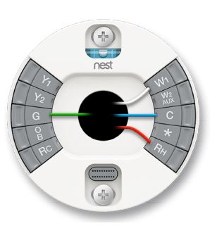
1st Stage Heat Pump (5 Wire)
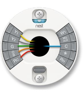
Remember that all heat pumps are going to need a wire connected to the O/B terminal. And a single stage heat pump will have a single wire connected to a compressor relay stage one( Y1) Altogether you should have 5 wires connected.
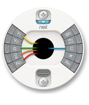
- Y1 Compressor Relay (Stage 1)
- G Fan Relay*
- O/B Heat Pump Changeover Valve
- Rc 24VAC power from cooling transformer
- C 24VAC Common Wire †
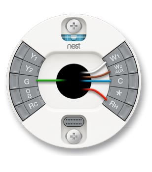
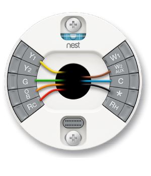
1st Stage Heat Pump with Aux Heat (6 wire)
A single stage heat pump with auxiliary heat will have 6 wires connected in total.
However, in addition to the Y1 connector, you are going to have the Aux connector also connected. See diagram below

- Y1 Compressor Relay (Stage 1)
- G Fan Relay*
- O/B Heat PuNest Thermostat Wiring and Diagrams Amp Changeover Valve
- Rc 24VAC power from cooling transformer
- AUX Auxiliary Heat Relay
- C 24VAC Common Wire
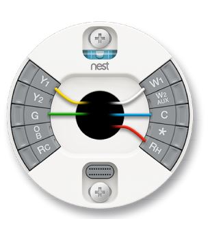
1st Stage Heat Pump with Aux heat and Emergency Heat (7 wire)
A single stage heat pump typically has one of the compressor relay connectors Y1 connected. Then for heat, you are going to have the Aux connector connected and the star for Emergency heat E. In total you will have 7 wires connected in total.
- Y1 Compressor Relay (Stage 1)
- G Fan Relay*
- O/B Heat Pump Changeover Valve
- Rc 24VAC power from cooling transformer
- W2/AUX Heat Relay (Stage 2) / Auxiliary Heat Relay
- C 24VAC Common Wire
- * Star: E
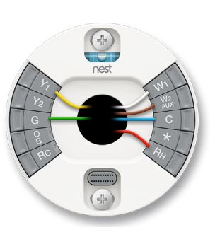
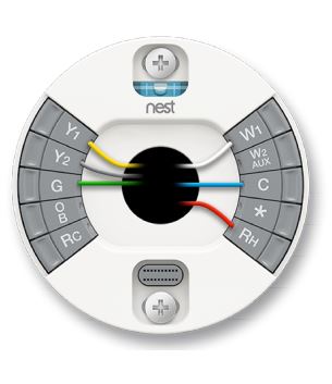
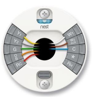
2nd Stage Heat Pump (6 wire)
For a 2 stage heat pump, both Y1 and Y2 will have wire connections and intotal you should expect to have 6 wires connected as shown in the diagram below
- Y1 Compressor Relay (Stage 1)
- Y2 Compressor Relay (Stage 2)
- G Fan Relay*
- O/B Heat Pump Changeover Valve
- Rc 24VAC power from cooling transformer
- C 24VAC Common Wire
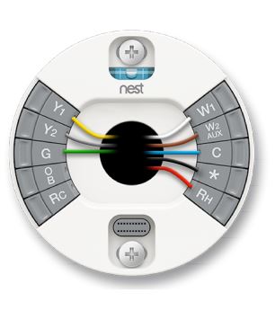
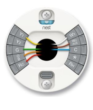
2nd Stage Heat Pump with Aux Heat (7 wire)
Another 7 wire nest thermostat diagram is for a 2n stage heat pump with Aux heat. I will have both the Y1 and Y2 wire connected but in addition , there is going to be a wire connected to the W2/Aux connector.

- Y1 Compressor Relay (Stage 1)
- Y2 Compressor Relay (Stage 2)
- G Fan Relay*
- O/B Heat Pump Changeover Valve
- Rc 24VAC power from cooling transformer
- W2/AUX Heat Relay (Stage 2) / Auxiliary Heat Relay
- C 24VAC Common Wire
Read also: Nest blowing hot air on cool setting
Wiring Diagrams for Dual Fuel Systems
Dual fuel systems have an advantage in that a heat pump will provide the necessary heating in mild weather conditions but in extreme temperatures where a heat pump will not deliver, alternative heating sources will provide the necessary heat.
Remember, the efficiency of a heat pump decreases with the drop in outdoor temperature. Wiring dual fuel systems is easy, you will just add the wiring for alternative heating as shown in the following heat pump diagrams
1 Stage Heat Pump, 1 Stage Heat (6 wire)
The dual fuel system has all necessary wires for a single heat pump connected then an additional wire in the W1( for alternative heating) is connected. The total number of wires connected is 6 wires.

- Y1 Compressor Relay (Stage 1)
- G Fan Relay*
- O/B Heat Pump Changeover Valve
- Rc 24VAC power from cooling transformer
- W1 Heat Relay (Stage 1)
- C 24VAC Common Wire †
2 Stage Heat Pump, 1 Stage Heat (7 wire)
A dual fuel system with a heat pump system and single stage heating system will have 7 wires in total. Wiring is also not sophisticated. Just do the wiring as you would do for a 2nd stage heat pump then add missing wires that you would connect for a single stage furnace. This is simplified in the diagram below.

- Y1 Compressor Relay (Stage 1)
- Y2 Compressor Relay (Stage 2)
- G Fan Relay*
- O/B Heat Pump Changeover Valve
- Rc 24VAC power from cooling transformer
- W1 Heat Relay (Stage 1)
- C 24VAC Common Wire
1 Stage Heat Pump, 2 Stage Heat (7 Wire)
- Y1 Compressor Relay (Stage 1)
- G Fan Relay*
- O/B Heat Pump Changeover Valve
- Rc 24VAC power from cooling transformer
- W1 Heat Relay (Stage 1)
- W2/AUX Heat Relay (Stage 2)
- C 24VAC Common Wire
2 Stage Heat pump, 2 Stage Heat (8 Wire)
A two stage heat pump system and a 2 stage furnace Dual fuel system has the most wires connected to the thermostat. That is simply because you have all the wires you connect on a 2 stage heat pump system with all wires connected to a 2 stage furnace combined. We have simplified this in the next diagram below
- Y1 Compressor Relay (Stage 1)
- Y2 Compressor Relay (Stage 2)
- G Fan Relay*
- O/B Heat Pump Changeover Valve
- Rc 24VAC power from cooling transformer
- W1 Heat Relay (Stage 1)
- W2/AUX Heat Relay (Stage 2)
- C 24VAC Common Wire
Wiring Diagrams for Fans
2 speed fans
The wiring of a two speed has only 3 wires. One wire for the 1st speed connected at the G connector, another for the 2nd speed connected at the Y1 connector. Take a look at the diagram below.
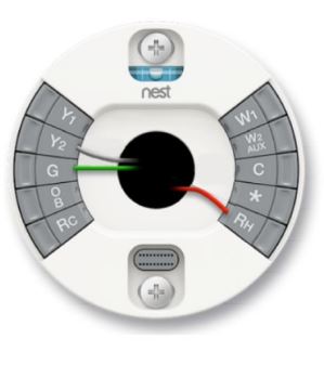
- 2nd-speed fan relay
- G Fan Relay*
- Rh 24VAC power from heating transformer
3 speed fan
The 3 speed fan has four wires connected to the terminals. In addition to the 3 wires on the 2 speed fan, there is an additional air connected to the start( for the 3 fan speed relay). See diagram below

- Y2 2nd-speed fan relay
- G Fan Relay*
- Star* 3rd-speed fan relay
- Rh 24VAC power from heating transformer
Testing The System After Wiring is Complete
1) Testing for heating and cooling
You will want to test the system after wiring the thermostat to ensure that the wiring has been successfully implemented.
To test for cooling: switch to ‘cooling’ and adjust the ring of the nest to set the temp point to lower than the current ambient temperature. Wait for at least 5 minutes and feel if the thermostat has started blowing cold air.
To Test for heating: switch to heat and turn the ring to adjust the temperature to a point higher than current ambient temperature. Wait For 5 minutes to see if your thermostat will start blowing hot air.
To select between cooling and heating mode, do this
- On your thermostat go menu by pressing the ring
- Select th heating and cooling icon
- Tru the ring to select between heat and cool and press the ring to select.
2) Testing 2nd Stage or Auxillary
To test 2nd state or auxiliary heat on a heat pump, start by turning off the auxiliary lock out and raise temperature to 4% in heat mode.
FAQ
How do you identify a C-wire on Nest?
While most thermostat manufacturers designate c to the common wire, there are still others that use B for the common wire. So if you are upgrading from an old thermostat that doest have a c wire you may want to appropriately identify and designate it. This is how you do it.
- You are using a conventional system
If you are using a conventional system and you see B connected to the current thermostat, then B is the common wire. Connect it to the C- connector.
- You are using a heat pump system
If you are trying to install a nest thermostat on a heat pump system and you see both the B and C wires on the current thermostat. Connect the B wire to the O/B terminal and the C terminal to the C connector.
However, if your current thermostat has both O and B wires connected to it, connect the O wire to the O/B terminal and the b wire to the c terminal.
How do I set Nest auxiliary or compressor lock out?
Not that,to set lock out temperatures, you’ll need wifi connotation for the thermostat to monitor outdoor temperatures.
By default, when the outdoor temperature is above 50 degrees, Nest will automatically lock out the auxiliary heating ( But does not lock out the compressor).
To change auxiliary or compressor lockout, go to the heat pump’s equipment settings by following the steps below
- Bring up the menu by pressing the ring
- Turn the ring to select settings
- Turn the ring again to select equipment and select the heat pump.
How to fix Nest blowing Hot air on cool and cold air on heat
If you have recently installed a nest thermostat and heat and cool are reversed, You’ll need to change the heat heat pump orientation, This can be done by following these steps below:
- Press the ring to bring up the menu
- Turn the ring and select ‘SETTINGS’
- Turn the ring and select ‘EQUIPMENT’
- Turn the ring and select ‘HEAT PUMP’
Read also: How to Find Entry Key on Nest Thermostat
In Summary
In closing, we hope that you have managed to correctly fix your thermostat and your system is working as it ought. Otherwise, it’s always best to consult professionals for help where you don’t feel comfortable doing it on your own. We have also added a quick table to quickly tell you the type os system that should be connect to a number of wires
| Number of wires | Type of system |
| 3 | 2 speed fans |
| 4 | 3 speed fansStage 1 furnace |
| 5 | 2nd furnace1st stage furnace and one stage ac1st stage heat pump |
| 6 | 3rd stage furnace2nd stage furnaces with ac1st stage furnace with 2 stage ac1st stage heat pump with aux heat2nd stage heat pump1st stage heat pump and 1 stage heat( dual fuel) |
| 7 | 2nd stage furnace with 2 stage ac1st stage heat pump with aux and emergency heat2nd stage heat pump with aux heat2nd stage heat pump with 1st stage heat |
| 8 | 3 stage furnace with 2 stage ac2 stage heat pump 2 stage heat |
![Carrier Infinity Thermostat Wiring To Nest or Honeywell [Complete Guide]](https://thermostating.com/wp-content/uploads/2023/04/carrier-infinity-wiring-768x429.webp)
![White Rodgers Thermostat Keeps Resetting to 85 [Fixed]](https://thermostating.com/wp-content/uploads/2023/02/white-rodgers-thermostat-768x395.png)
![Nest Thermostat No Heat Option [Causes and Fixes]](https://thermostating.com/wp-content/uploads/2023/08/nest-no-heat-option.jpg)
![White Rodgers Thermostat Wiring to Nest [How To]](https://thermostating.com/wp-content/uploads/2023/04/white-rodgers-to-nest-jpg.webp)
![Aprilaire Thermostat Says Off [Super Easy Fix]](https://thermostating.com/wp-content/uploads/2023/03/aprilaire-thermostat-768x426.webp)